The description below is biased in favour of being verbose and detailed at the risk of being preachy and pedantic. If you've done this sort of thing before you don't need my help. If you haven't done this sort of thing before, not only will you want all the help you can get, but you'll also want to learn from (and not repeat) all of the mistakes I made. Wherever possible, I've got pictures of all the relevant stages of the process as well as a few others taken after the fact to highlight some important details. It is important to note that Richard has done this sort of thing a lot, which means he's very experienced, but also means that he is bound not to mention all of the details that are necessary because he takes them for granted. I have tried to mention all of the tricky little bits that came up whether he mentioned them or not. For example, dealing with the battery heat shield was for me a surprise when the problem came up, but when I mentioned it to Richard was an "Oh yes, now you come to mention it, you'll have to do that too" kind of job.
As is the way with most car activities in my experience, this project took about 1.1 people. You can do almost everything on your own, but there are a lot of times when you need an extra pair of hands for five minutes. You'd want to make sure that you have easy access to such assistance. Presumably someone with more experience could make do with fewer requests for help, but I certainly couldn't. Had I not had someone else there to help me at short notice I would have spent a lot of my time twiddling my thumbs waiting for help, which would have stretched the project out enormously. As it was, I think I spent about twenty full days on it, but most of the work got done over two solid weeks of work. Even so, it was still about two months from the time the motor arrived to the day I was able to drive the car regularly.
Of course, an old motor is not the only problem with a Europa. Like any Lotus, and most British cars in California, cooling is always a problem, so I was determined that I would not risk my nice new motor by not upgrading the cooling system. My strategy was twofold. First I would re-core the radiator and would then put in a new fan. The original fan had the problem that in the rain (remember, this is my wet-weather commuting car), even with a little water deflector plate mounted over fan motor, water would get into the motor bearings and would wash out the oil. Regular lubrication of the fan was the only thing that seemed to keep it going, and it was always noisy, vibrated horribly, and was not very powerful-seeming.
To add to these problems, the fan switch (otter switch) had clearly failed before I bought the car and a manual switch had been installed under the dashboard. This meant that you had to be alert enough to turn on the fan. The reason why the original switch had not been replaced was presumably that the switch is mounted in a silly rubber grommet. Monkeying with it at all increases your chance of the whole thing popping out, so the previous owner had clearly decided that it was better not to monkey with it. There is a common minor modification that puts a little L-shaped piece of metal clamped to the bottom coolant hose that points up next to the otter switch to stop it popping out. Given that I was going to have the radiator out to re-core it, I planned to put in a new switch arrangement to fix this design flaw, and replace the fan with a decent modern one.
So, a couple of weeks before the new motor actually arrived I made the tour over to the East Bay, where there's a wrecking yard specialising in Mercedes. There, I got an auxiliary fan made by AEG that's really nicely made and designed to push rather than pull as most radiator fans are. It's nice and powerful and ended up costing $50, which seemed little enough to pay for a really nice fan. It turned out that the fan I got was in fact a new one that was left-over stock, so I think I did pretty well.
Next I got a new fan switch. I believe it's for a GM Horizon. It has a 3/4" tapered pipe thread fitting, which is nice and generic. This meant that I was able to go to the local hardware shop and buy a 3/4" pipe thread coupler, and cut it in half to leave me with a short threaded copper section that would be easy to solder into the radiator.
As it happens, I also milled a couple of flats onto the sides of the fitting to make it easy to get a spanner on to relieve any strain whilst tightening up the fan switch, but when I got the radiator back from the guy who did the work, he had mounted it flush so there was no way I could get a spanner onto it, but he said it was plenty strong, so there was no need for me to have gone to such trouble. As far as I can tell, he was dead right.
Another job I did before the motor arrived was to take out the fuel tanks. I already had one alloy tank and one original steel one - one of the original tanks had rotted out a year before. The tanks needed to be modified to add a return pathway for the fuel injection. Never having had to worry about this sort of thing before, I had never focussed on it, but the way the fuel injection works is to have a high pressure fuel pump (well over 50lbs) pumping fuel to the injectors which are mounted on a rail. At the downstream end of this fuel rail is a fuel pressure regulator that regulates the pressure down to 50lbs. The outflow from the regulator then needs to be fed back into the fuel tanks. The flow rate is such that is you feed the back-flow into only one tank it runs the risk of overflowing the tank because the flow in the balance pipe between the tanks isn't good enough. Thus, you need to put fuel return adaptors into both tanks.
I decided that I might as well get a second alloy tank made to match the other, and have them put a return into the tank they had made the previous year for me at the same time. New tanks seem to cost about $400 off the shelf in the US, but I found a place who made me my tanks on a one-off basis for about $200 each including the fuel level sender. I had them put a fuel level sender into both tanks - the cost was far less than the pain of pulling a tank if a sender were ever to fail, though the senders are apparently generic GM parts. If you ever need tanks made I highly recommend Roy-ol Industries in San Leandro, CA, 510-351-0300.
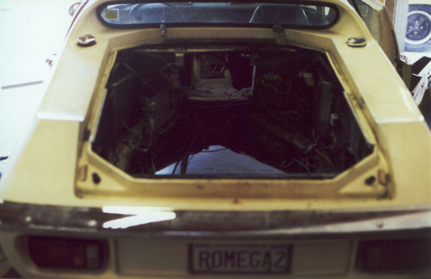
The new fuel tanks are visible on the work bench behind. By this time, I had already taken the bonnet and boot off the car, but didn't want to start any really serious dismantling until the new motor actually arrived. A number of the operations that I was to perform were irreversible, so I didn't want to do anything unless I was pretty confident that I wouldn't get stranded with a big pile of non-functioning and non-mobile bits.
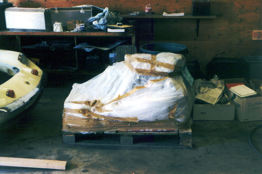
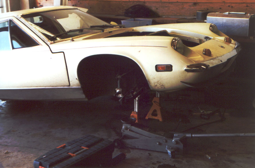
Figure 2 is a view of the car just before I started work. I was beginning to ferry tools and other bits-and-pieces over from home to the garage, both so as to minimise my impact on my friend's business, and because I knew I'd need a number of tools that are unlikely to be in the average garage. Just beside the right rear wheel are a Sawzall (a reciprocating saw) and a big angle drill. The 2-by-4s on the floor are in anticipation of needing to make sundry wooden frames to hold things up. Unlike most cars, when you take the motor out of a Europa it's unable to stand up on its rear wheels, so you have to keep it on jack stands throughout the job. Behind the car up against the workbench are the bonnet and boot. On the workbench to the far right is a toolbox/stepstool. This proved invaluable. I spent a lot of time either sitting on it or standing on it to get a better reach into the engine bay, since I used tall jack stands. Tall jack stands made it easier to crawl around underneath to work on things like the motor mounts and fuel system plumbing. I got an extra-tall pair of jack stands for the rear and set them at the rear under the chassis just next to where the rear hoop meets the chassis after the old motor came out.
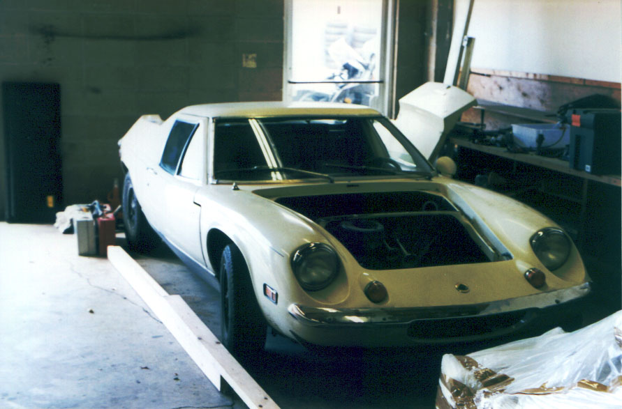
Figure 3 shows the state of the old motor just before I started work, looking down and forwards into the engine bay from the left rear corner of the car. It all looks rather old and knackered, but it worked well right up to the day I pulled out the fuel tanks. The motor was a twincam that had been rebuilt once a long time before I got the car, replacing the original Stromberg head with a Weber one. The car had about 115k miles on it when I started this work, which is fairly high for a Lotus. I gather that the previous owner drove it twice across the US.
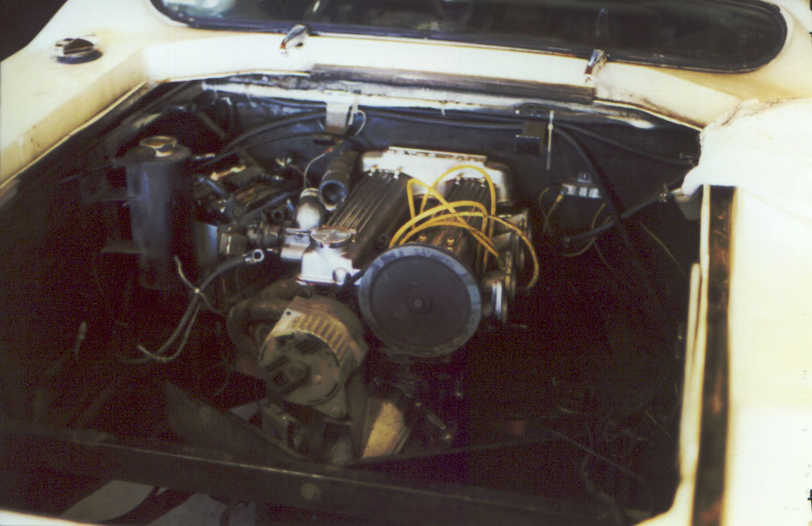
In this motor configuration, because the engine bay is pretty tight, the alternator is driven from the end of one camshaft rather then from the crank pulley as one finds on normal cars. The new motor has a similar arrangement, but unlike this motor, which has a distributor drive lurking under the carbs, the new motor has to drive the alternator from the end of the camshaft where the distributor would have gone originally. This means that the new motor has to have distributor-less ignition, since there is nowhere left to put a distributor.
Also of interest is the exhaust. On the old motor, the exhaust headers snake down under the sump, join, and the exhaust then comes up on the right hand side of the motor to the muffler at the back (bottom right of picture). In the new motor the exhaust is routed differently. Running across the engine bay at the bottom of the picture is the rear chassis crossbeam. This part is to be replaced by the new twinlink suspension. The diagonal braces that connect the sides of the chassis to the centre of the crossbeam are removed entirely when the twinlink is installed.
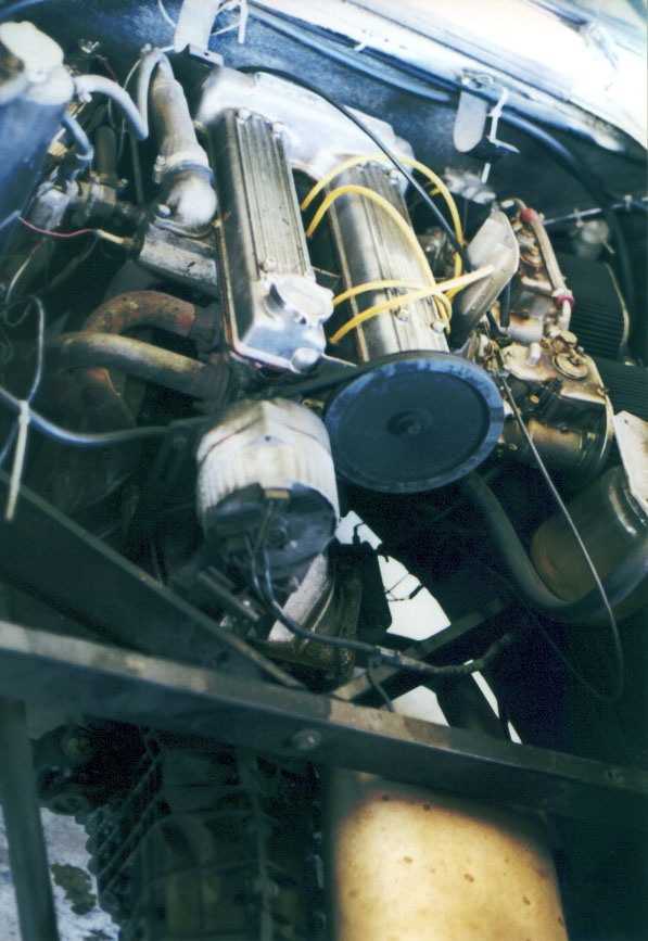
Figure 4 shows the state of things when I unwrapped the new motor to make sure that everything had arrived. The motor, clutch and gearbox all came together complete with the front end of the exhaust and all of the wiring and fuel injection stuff already in place and ready to drop into the car. The motor mounts were already on the motor, and these were used to bolt the motor to the palette for shipping. Also sitting on the palette in this view (from the left) are the new swirl pot, coolant plumbing, the muffler, chassis rear hoop, tail pipe and shift linkage. Visible on the floor (from the left) are the new front hubs, discs, brake shoes and calipers with the fuel pump/filter assembly behind, the new shocks, and finally the twinlink suspension bits with the twinlink chassis crossbeam behind.

Before starting work on a project like this there are a couple of issues that you might want to organise before you start above and beyond the obvious issues of trying to get all of the tools and parts in place. Whatever you do, you're going to end up oily and dirty all over, and you're going to need to wipe up significant amounts of nasty mess, be it sticky black Dunlop glue from the bottom of the radius arms or coolant that's going to leak everywhere and keep dripping for days out of the little bit of foam at the front of the engine bay in the spine of the chassis. I was lucky to be working in a commercial garage because I was able to take advantage of the shop towel cleaning service there. The deal was that they gave my friend hundreds of shop towels each month at a fixed price. Since he never used them all up I was able to use his spare capacity to keep things clean.
You might want to investigate some local garage or machine shop to see if you can work out a deal with them both for shop towels and for overalls or other work clothes. Cleaning this amount of dirt at home in your washing machine will not make you popular with the rest of the family.
Another tip that I picked up from Eric was to use disposable rubber gloves a lot of the time. You lose a bit of feel, and they do disintegrate after a while, but you do end up a lot cleaner at the end of the day. The best ones seem to be the ones that have Gortex in them. They seem stronger, and have a slightly rough surface that seems to grip better. The cost about $9 for a box of 50 pairs, which is not a lot in the grander scheme of things.
The first step, not shown in any picture was to drain the coolant system and pull out the radiator. As far as I can tell, there isn't a good and clean way to drain the coolant. I did so by removing the bottom hose at the radiator, and then all of the coolant drained out through the hole in the floor of the front boot. Unfortunately, once it went through the hole in the floor, it spread out on the top of the belly pan that runs across under the steering rack, and coolant then dribbled out either side all over the place, making it very hard to catch in a drop tray. If I were to do it again, I think I'd jack the car a little on one side in the hope of trying to get the coolant all to pour out one way.
Once removed, the radiator then went to the radiator shop next door to be re-cored and have the fittings soldered on for the new fan arrangement. Once this one was done I was able to get started on the front brake and suspension rebuild.
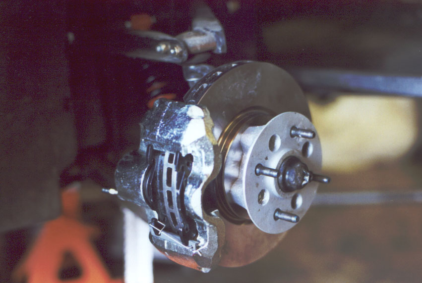
In figure 5 you can see things after I had dismantled everything, leaving the stub axle bare. It turns out that replacing the front shocks is a major pain, since the whole arrangement is under a certain amount of tension. The sway bar, which attaches to studs on the bottom of the dampers is difficult to get unhooked. The top mounting bolt for the damper has to be removed by pulling back some of the carpet in the cockpit and pulling out a rubber blanking plug to get access to the long bolt that holds the whole assembly together. This is really difficult to get out because there's no good way to get into the wheel well to get any leverage to push the bolt out. The jack is sitting under the assembly in the picture because you need to jack a bit to relieve some of the tension. In my case on one side of the car my problems were compounded by the sway bar having been tightened up so much that one of the washers had distorted and jammed onto the thread. This took considerable leverage and effort to remove. After this, assembly seemed pretty easy by comparison.
In figure 6 you can see things after I had put things together. The AVO dampers I had got were considerably smaller in cross-section than the original ones as well as somewhat shorter, which made them easier to deal with. However, they also weren't quite as wide at the ends, so I had to shim them with washers. Having to go and buy a bunch of 1/2" fender washers to fit the dampers was the only reason I had to go to the hardware store, at least to deal with any parts I had got from the UK, in the first ten days of work. I did have to get other parts to deal with fuel line plumbing and the firewall modifications to come, but I was very impressed by how complete everything was that came on the palette. This was a clear advantage of having the whole thing built in a chassis before shipping.
The astute reader will observe that I had screwed up the brakes in two different ways. First, the brake pads came with a bunch of little spring gizmos to secure the bar that holds the pads in. I had no idea how these worked, and the little spring holding them in was a temporary fix until I called up Richard. The answer was to throw away the clips I used in the picture and use the other ones. The more serious problem was that in a moment of brainlessness I had put the calipers on swapped left-for-right. You can tell this by the bleed nipple being at the bottom of the slave cylinder at the back of the caliper, rather than at the top. When I came to try to bleed the brakes they bled down fine, but because of the air trapped at the top of the slave cylinder, the pedal kept going straight to the floor.
A couple of issues arose whilst working on the front hubs and brakes that it seems worth mentioning. As can be seen easily from the condition of the hubs as they came on the palette in figure 4, there are no studs for the road wheels. This meant that I had to remove the old studs from the old hubs and put them into the new ones. This was pretty easy to do by putting a couple of nuts onto each stud and then hammering it out of the old hub. To put the stud into the new hub one had only to twist it until the splines were well lined up and then hammer a bit. This seated the stud into the hub, but didn't anything like get it set all the way in. To get it all the way in, I packed a pile of washers over the stud and then tightened up a nut on the stud, which pulled it into place.
The new hubs were nice and clean and bead blasted smooth, but they still had the old bearing races in. These had to be removed and the new bearings inserted. Again, it was fairly easy to do this. I was able to remove the old races by drifting them out. The new ones I was able to press in using a monster bolt with spacers of the right diameter to fit the outside of the races. A hydraulic bearing press would have been nicer.
If you are in any way reluctant to deal with pressing in bearings or studs, you should probably either get Richard to do this before shipping, which he would presumably do at a nominal charge, or get a local machine shop to do it.
The new discs had to be bolted to the back of the new hubs. This turned out to be more of a problem than I had expected, since it turns out that the inner flange on the new vented discs through which one bolts to the hub was slightly thinner than the old discs. This proved to be a problem because the old bolts were a hair too long to go in and tighten down flush. If you have any problem getting the bolts to tighten down properly on the disc, you might want to do as I did and put a washer in.
Once you've got the hub and disc fully assembled you can put it on the car, making sure that you pack the hub with suitable high temperature grease bearing, and that you put the felt seal on the right way round between the hub and the stub axle. The brake calipers can then be attached (making sure you get them the right way around). The brake pads only seem to be able to go in one way, so there's no danger of getting it wrong. Apparently, the preferred location for the locking bar it at the top, unlike as is shown in figure 6.
Once I had finished putting the front brakes and suspension together I was ready to take the old motor out. The first thing to do, of course, is to disconnect all of the wires and cables and hoses that will stay with the car. Initially, I tried writing down all of the bits I disconnected, but after a while I gave up - laziness on my part, but I managed to convince myself that ultimately, as long as I found the right place to hook up everything I should be fine. As can be seen somewhat in figure 7, there are a lot of hoses and wires to disconnect. You're bound to miss something, so when it comes to taking the motor out you need to keep looking around and be ready to disconnect any remaining cables of hoses. The motor can come out either by dropping it down and lifting the body off the top, or by lifting it out the top. Since I had a lift available, I decided to drop it out the bottom. In retrospect, my guess is that it would have been easier to hoist it out upwards. If you plan to drop it out the bottom, you'll need a lift, and you'll need to take the carbs off as well as everything else.
When you think you've got all of the cables and hoses disconnected you can think about actually removing the motor. All that should be holding it in at this point are the motor mounts on either side of the block, two 1/2" bolts at the back of the gearbox, and the bolts securing the lower suspension links.
However, before you actually take the motor out, you should probably think hard about how you're going to get the hub nuts and hubs off. It is possible that when you come to do this part of the job your car will be sloppy and ready to fall apart, but if mine is in any way predictive, this will be one of the really nasty bits. You should think about this at this point because you may find it easier to loosen these parts at this point in the disassembly of the drive-train, with the drive shafts still in place in the gearbox than if you waited until after the motor was out. Once you've got things apart you can still put the hubs back on loosely if you need to move the car before you take the motor out. I didn't do this, and things were a lot harder later on.
The trouble is that in order to compensate for the structural inadequacies of the original parts, which are under severe loads in all directions, the rear hubs are glues to the splines on the stub axles and the hub nuts are similarly glued onto the stub axles with red Loctite (the stuff that's supposed to be used for permanent assembly). Just looking at the assembly, you'd think that you should be able to take the whole thing apart by bending back the tab washer and removing the nut and everything should just pull off. Looks can be deceiving.
The trouble is that with all of that Loctite there, you have to apply enormous torques to get anything to move. This is hard to do because there's no good way to lock the drive shaft. What I ended up doing was wedging a tyre lever into the U-joint and putting a really long bar on it, and then taking a socket to the hub nut also with a really long bar. Having the drive shaft supported at the inboard end would make it a lot easier to stabilise. This arrangement sufficient to move the hub nut, but taking the hub off turned out to be much harder still. Even with a monster puller and enormous torques, it still wouldn't budge.
Ok, so much for how not to do this, now on to how I would do it if I were to have to do it again. First off, I'd make a magic tool out of a piece of steel plate that has four holes to match the studs for the lug nuts and a big hole in the middle large enough to accommodate the tab washer in its flat state. A final square shaped hole sized to fit a 3/4" socket square drive finishes off the device. I made one of these on my mill at home. For all I know you can buy them, but you could easily have a machine shop make one. Using this tool to put the hub assembly back together was a piece of cake. Anyway, once you've made this tool, bolt it to the hub with the lug nuts, stick in the 3/4" bar, and then play a blow torch over the hub for a long time. It would appear that the heat degrades the Loctite, so as long as you keep the blow torch on you can get the hubs off suffering only occasional and mild hernias.
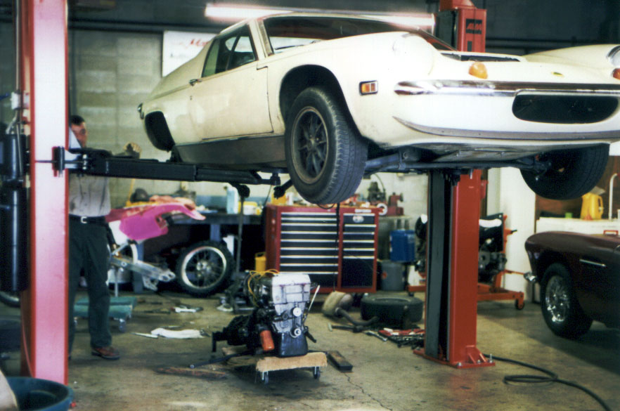
Figure 8 shows the state of play just before the old motor came out. The car has been positioned in the lift and the rear wheels have been removed. This allows the car to be dropped low enough that the motor is sitting on a furniture dolly. Once this is set, you can remove the motor mounts and other bolts securing the motor, and start to lift the car.
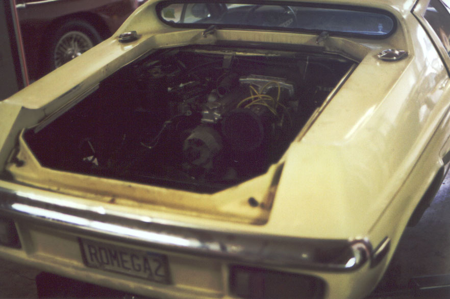
Figure 9 shows the motor as the body is starting to be lifted off over it. If you don't have a lift, the thing to do would be to remove the rear chassis crossbeam and hoist the motor out from the top. Because I was dropping it out of the bottom of the car, I left the lower links on the gearbox, and disconnected them from the bottom of the hub carriers. Note that when you release the suspension links the drive shafts will still be attached to the output of the gearbox with roll pins. You'll need to drift these out. Once the drive shafts are free and you start to take the motor out the drive shafts will drop off the end of the splines on the gearbox. This will leave the rear hub assemblies unsupported on the radius arms. You should tie the radius arms up to the chassis to make sure that you don't damage them.
In my case, I got this far and discovered that I had failed to disconnect the speedo drive, but had otherwise managed to get everything out. It would be a good idea to take the motor out slowly and check regularly not just that it's clearing everything as it comes out, but also so that you really have got everything disconnected.
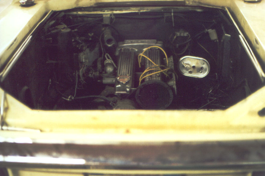
Figure 10 shows the motor just after it had dropped out of the bottom of the car. In my case, the dolly collapsed, hence the funny angle as it sits under the car - too many pianos and heavy bits of furniture moved over the years on this one, I fear. Luckily, it was still easy to push the motor around on the two remaining functioning wheels. Note also the drive shafts dangling down in the middle of the car - the radius arms are already supported.
I wasn't going to be able to leave my car on my friend's lift so we dropped the car back down onto another furniture dolly resting on the rear hoop, and with the inboard ends of the drive shafts also sitting on the dolly. This left the car surprisingly maneuverable. It was easy to push around simply by pushing from the back without even needing to steer. This allowed me to get the car outside so that I could steam clean the engine bay.
Even if you are doing this at home and don't have access to a steam cleaner, I would strongly advise using the best and most vigorous cleaning strategy that you can. I screwed up by not cleaning enough up under the rear wheel arches, and suffered from oily, dirty crumblies falling on me as I worked on the back of the car. Alternatively, you could always drive the car to a stream cleaner before you start all the work, but it's much harder to clean things properly when there's still a motor and all sorts of other bits and pieces in the way. A really good cleaning makes the whole reassembly process much more tolerable. It's irksome to be putting a nice shiny new motor into a grubby engine bay.
With the engine bay cleaned out you can start the (significant) preparation for the new motor. Although the new motor will fit in easily, there's still a lot of work to do. First of all, you need to take out all of the bits that aren't going to be reused. This included, in my case, the coil, the fuel pump (I had an electric fuel pump), the chassis cross beam, the old coolant header tank, and so on. In my case, the shift linkage was also being changed, so that went too. To get to the shift linkage at the front you have to remove the centre console.
There's a pipe welded on to the inside left of the engine bay that runs from the bottom of the coolant header tank to the front of the engine bay. This has to come off. I got it off with a cold chisel and a bit of levering, but you could just as easily grind it off.
I should note at this point that in my car the brake servos had long before been removed. You'll need to decide whether you're going to do any brake system plumbing. This is the ideal time to do it. The normal location of the brake servos is also an ideal location for the new swirl pot, so you should think about this issue. If in doubt, you should check with Richard to make sure that the brake and coolant plumbing locations are going to be compatible. If you plan to keep your servos you'll also have to make sure that a suitable vacuum point is provided on the throttle bodies. Mine does not have one.
The next job I tackled was to make the hole in the firewall. This accommodates the motor, which is a hair longer than the original. The strategy is to shim the firewall out on the inside of the cockpit and then put a hatch cover on. As it happens, this turns out to be a really good idea, and in retrospect, even if I were just to have been putting a twincam back in, I think I would have put such a hatch into the firewall. From the hatch it's possible to service the water pump and change the cam belt without dropping the motor out. I also found that being able to work through the hole made life easier in a number of minor respects, each of which saved time.
Before you can make the hole, you have to remove the cockpit's rear trim panel. This is held on by two things that looked like screws (they had slots on the heads), but turned out to be nails driven into things that looked like wall plugs. The thing to do is just to lever them out or pull them out with pliers. This reveals the cockpit side of the firewall. The hole should be as wide as the outside edges of the spine of the chassis as seen from inside the cockpit, should go down as far as about 3/4" from the top of the spine of the chassis with the carpet pealed back, and should be as high as possible. In my case, there was a tube running across the front of the engine bay. I believe that this piece is probably only on later Federal models of the Europa. My hole was to come right up against this tube. I did the sawing by marking out on the cockpit side of the firewall, and drilling through in the corners and then cutting with a Sawzall. I needed to have someone looking in the engine bay because I ended up cutting very near wires, so having someone there to push the wires aside and tell you when to stop was a good idea. When you cut the hole, make sure that you cut it as close as possible to your intended size, since you can reuse the piece you cut out when you make the hatch. This hole can be seen in Figure 11.
Having been destructive for a while, I decided that I'd like to put something together for a change. My goal was to have effectively all of the dirty drilling and sawing done before I put the new motor in. Since I was going to install the twinlink suspension, the next step there was to install the mounting brackets to the hub carriers. This, in principle, simply involved removing one bolt (the top rear one, which is the furthest right one visible in figure 12) from the outside of the back plate of the brake drum and drilling out the thread (check with Richard for the right drill, I've lost my notes on this one). This is also done on the other side (the engine side of the hub carrier) and then the twinlink bracket should just slip in between the ears at the top rear of the hub carrier. This almost worked for me. I found that the casting of the hub carrier was not terribly even, and that I had to grind away a little in the corners to make way for the twinlink bracket.
Thanks to Richard, all of the bits of the twinlink had been labeled on bits of masking tape, so I wasn't left scratching my head trying to offer up a piece for the wrong side of the car. Once the bracket was bolted into place, the bottom lobe of the bracket hung down at the bottom of the hub carrier. This marked the place where a new 1/2" hole was to be drilled. The bolt through this hole takes the bottom shock mount. Another hole that is already there is used for the lower link. I think that some hub carriers that have been used for race applications already have a second hole. If this is the case on your car, you should probably let Richard know before hand just in case this affects things.
I have to say that drilling this hole was a long, noisy and uncomfortable job, sitting on the floor drilling away, but I got there in the end. Once this was in place, I could drill the final two holes that are used to affix the back of the twinlink bracket to the hub carrier with self tapping screws (check with Richard for drill sizes). These are apparently not that important structurally speaking.

Once the hub carriers were ready, I got on with installing the new twinlink crossbeam (figure 13). This has mounting holes predrilled that mate with the holes for the old crossbeam. You need to enlarge the holes in the bodywork around the shock towers substantially to accommodate the new crossbeam - more work for the Sawzall. Once you've got the holes enlarged, the crossbeam can be dropped into place. You should not drill the final two holes in the middle at the back of each side piece until after the motor is in place. This will allow you to make sure that everything is upright and correctly clears the gearbox.
In my case, there were diagonal braces that used to bolt to the top of the shock towers that stabilise the seat belt mounts. I gather that these are rare, and only appear on some Federal Europas. Because the top shock mounts are moved back by a couple of inches on the twinlink, there were no holes on the twinlink crossbeam to secure these braces. I had to drill 1/2" holes for these - again this was a bit uncomfortable, but not a problem as long as you've got a suitably powerful drill that will fit up into the wheel well. I have a heavy-duty angle drill that worked well. I could have marked the holes by scribing through the braces and then drilling on a drill press, but drilling through the braces seemed the best way to guarantee alignment. Once this is all in place, you can easily remove the crossbeam - it needs to come out in order to get the motor in.
Given that by now you've got all of the unnecessary bits out of the engine bay you'll probably find it to be a good time to do a little painting. I certainly found that a lot of paint flaked off when I steam cleaned around in the engine bay. If you paint, you should make sure to mask around not just the obvious bits that might be marred by getting matte black paint on them, but also the tail ends of the wires that will be dangling around the engine bay. Although the wiring diagram may be a work of speculative fiction, you'll find it much easier to figure things out if the colour codes are not masked by paint.
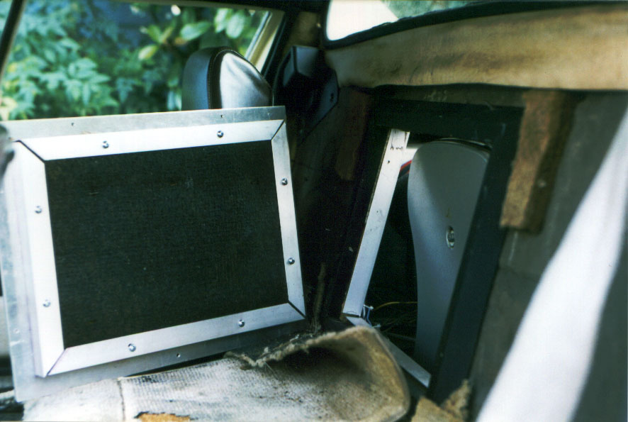
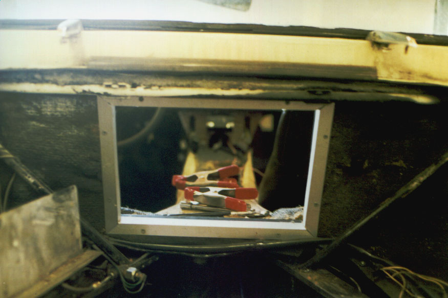
Next, I made a cosmetic frame to go on each side of the hole in the firewall. On the cockpit side, I took some 3/4" (1-by) wood and ripped a 45 degree bevel into it and then ripped it to width so that the width on the shorter face was about 3/4". I could then make a frame that had 3/4" of meat for screws to grab from behind, and that sloped away from the hole to the firewall. I mitred the corners and screwed forwards from inside the engine bay into the wooden frame by pushing aside the sound absorbing felt. It didn't matter too much how neat I had got the hole because any unevenness was disguised by a frame that I made for the inside of the hole from the engine bay side. I made this from 1"x1" L-section aluminium extrusion that I got from the local hardware store. After predrilling and countersinking holes, the frame screwed into the wooden frame on the other side of the firewall trapping the dangling pieces of sound absorbing felt and leaving a neat hole shown in figure 14. This picture is looking through the hole into the cockpit from the engine bay. Visible through the hole are some of the spring clamps I used to hold things in place once they were squared up. Squaring was done with a simple carpenter's square. In my case, the hole came close enough to the top of the chassis spine that there wasn't quite room to put in the beveled piece of wood at the bottom, so I put in a 3/4" square piece instead.
Visible on the left of figure 14 is the heat shield for the battery. I found that once the motor was in place that the heat shield fouled the exhaust, which is quite a bit bigger than that on the original twincam. I ended up cutting off the old heat shield, moving the battery towards the fuel tank by about an inch, and putting a new heat shield in place. I then also made another heat shield that curved over from the battery tray to protect the brake pipes that are pretty close to the exhaust. This was all a little tricky to do with the motor in place (though made easier by the hole in the firewall). I would council moving the battery before you put the motor in.
When I offset the battery, I held it in place with a piece of L-section extrusion left over from the firewall hole. Because there was no good way to move the holes for the battery bolts (they're right up against the edge of the chassis) I found that I had to make new battery bolts out of a length of studding cut to length. I found that it simply wasn't possible to buy battery bolts that were any longer than the standard length. Making the battery mounts from studding had the advantage that I was able to make them a little long and then tune the length by putting a nylock nut on the bottom end. If you don't like this approach, you can always move the battery altogether either to the right rear quarter behind the wheel well, or into the front boot. Either of these options will require a certain amount of rewiring, of course.
The new heat shield arrangement is shown in figure 15.
This picture is taken looking through the firewall into the engine bay. The heat shields are the shiny pieces with the lower one curling over the brake pipes. Somewhat obscuring the view of the lower heat shield in the centre of the picture are the two wires for the temperature senders.
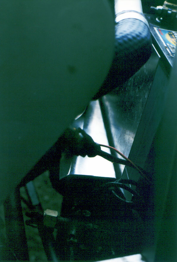
Figure 16 is a view of the same heat shield assembly taken from the back of the engine bay. This shows how a piece of L section extrusion was used to offset the battery, and how the heat shields bolt down onto the chassis, together with the extrusion.
When I had finally finished the whole thing and started driving the car, I found that I had a number of unpleasant squeaks. These came from where coolant pipes pass through a bulkhead in the spine of the chassis. There are grommets there, but after 25 years I suppose they had worn out. The pipes can bang up and down and squeak forwards and backwards. Given that you've got the engine out, I would strongly council changing these grommets. I wish I had. I've managed to retrofit some pipe clamps and a bunch of zip ties in, but doing the right thing when the engine was out would have been easier.
The coolant pipes have to be modified for the new motor by shortening them substantially. The new pipes will connect up to the old ones in the obvious way. The pipe from the swirl pot on the left of the motor will mate with the coolant pipe on the left of the spine of the chassis, and the pipe on the right of the chassis will mate with the hose coming from the water pump in the right. Similarly, the left heater hose mates with the top left heater pipe in the chassis, and so on for the right hand heater hose.
Both of the original pipes have to be cut short pretty much at the spine of the chassis. In particular, the right-hand pipe has to be cut short forward of the junction that used to connect to the old header tank. The left pipe has to be cut forwards of the lower bend - yes, all of the big curve that came up to the top of the old motor gets cut off. I cut the pipes again with the Sawzall. You should make sure that you clean up the pipes after you've cut them. You don't want nasty chunks of metal screwing up your water pump.
The next thing to do was to install the shift linkage. This involved mounting the rocking gate assembly against the front left of the chassis in the engine bay. To get the shift linkage into place one could assemble the shift lever onto the rest of the linkage by working through the hole in the top of the chassis spine, as I suppose the original linkage was assembled, but you need really small hands to do this and there's the constant irritation of dropping the bolt down into the bowels of the chassis. I found that one could enlarge the hole in the bulkhead in the chassis spine through which the shift linkage runs a bit (with a Sawzall, again), and it was then possible to pass the complete shift linkage in from the back. This made life much easier. Note that the rocking gate shift linkage is much floppier (until fully connected) than the original linkage for the 365 gearbox. You might want to remove the rear piece before offering it up just to stop it from flopping around.
Attaching the rocking gate is done by putting the shift lever on the end of the new linkage and bolting it in the chassis and then moving the rocking gate around on the chassis until the linkage coming back from the shift lever is perpendicular to the next segment in the linkage and is axial with the chassis. This all has to be done whilst someone else holds the shift lever upright. Once the position is established, the rocking gate is clamped to the chassis, and then the chassis is drilled and the rocking gate is secured with four bolts.
I found that it was pretty tough to get the bolts in place, since the bodywork at the front of the engine bay gets in the way. This would be much easier with the body off the car, but is possible with the body on given a little persistence.
I found that once I had the shift linkage in place and tried to see if I could get full motion out of it, the bottom of the linkage at the rocking gate fouled against the bent-over top of the bit of chassis stiffening that supports the front end of the radius arm. I gather that it it pretty normal to have to grind this bit down flush with the rest of the stiffening bracket. Of course, to get this right you have to take the rocking gate out again, so be prepared to experiment a bit, and don't go to lots of trouble bolting it in tight until you've guaranteed full motion of the shift linkage.
The last major job to do before the new motor could be put in was to cut out the old rear hoop and to offer up the new one. For all I know, this may not be necessary for some other versions of the chassis, but it certainly was for mine. By far the hardest part is cutting out the old hoop, since you have to grind out pretty well every last vestige of the old one before the new one will go in. I found that the best thing to do was to bite the bullet and simply cut the old one out up right next to the chassis on both sides with a Sawzall - otherwise it just got in the way of the grinding. Once the majority of the old rear hoop was out of the way I could take the angle grinder to the remaining bits.
This job is clearly much easier with the body off the car. Richard had said that I could release the rear-most couple of bolts that secure the body to the chassis and then jack the body a bit away from the chassis to make it easier to grind. I tried this and completely failed to make it work for me. I ended up simply cutting out the sections of the bodywork that got in the way. Considerable care has to be taken with this phase, since not only can you easily hurt yourself with an angle grinder, it's also easy to slip and punch a hold through the car.
Once the old rear hoop has been cut out you can offer up the new one. Keep grinding away until the new one fits in without too much hammering - remember that you'll be putting the rear hoop in for final assembly once the motor is in place, so there will be less room for any grinding or hammering. The rear hoop is asymmetric even though it looks at first sight that it's symmetric - the bend is offset - so either you need to make sure that the hoop will fit in either way around, or you need to make sure that you've figured out which way around it goes.
At this point I was pretty much ready to put the new motor in. Since the motor was out, I took the opportunity to do a few more jobs that might have been harder otherwise. I installed a new heater cable. The heater control on the new motor is on the right, and it works from the back, so you need to make sure that you've got a cable that's long enough to snake around and come in from the back. You might also think about putting in a new throttle cable. Mine was completely shot.
The hatch to cover the hole in the firewall was made by getting a piece of aluminium plate sized to fit the frame on the cockpit side and then cutting the remaining piece of firewall and sound padding left over from the making of the hole, and securing the firewall piece to the plate with another four pieces of L-section extrusion. I drilled through the plate and tapped the holes so that I could bolt the firewall piece into place securely and neatly.
The end result is shown in figure 17. This shows the hatch cover leaning against the seat inside the cockpit, and shows the details of the frame around the hole. When the hatch is in place, all you see is a flat aluminium plate with a beveled black frame around it. Of course, this will ultimately be covered by the firewall trim panel.