Once the motor mounts at the front were finger tight, the rear hoop was installed, and then the gearbox mount bolts held the rear hoop in place. The front motor mounts could then be tightened up. At this point, the motor seemed to be solid enough that the hoist could be removed. Because I'm paranoid I left a jack under the gearbox until the rear hoop was tack welded into place.
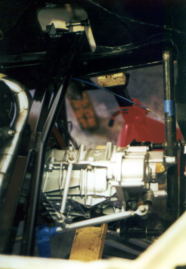
Since the next major step would be to tack weld the rear hoop into place, and then really to start putting things together, I carefully worked around the motor making sure that everything seemed to fit and that there was nothing obvious that might cause me to have to take the motor out again. For example, I connected the shift linkage and made sure that it seemed to work properly, and I put in the crossbeam and made sure that it didn't foul the reverse gear switch on the side of the gearbox. This can be seen in figure 19. I made extensive use of blue masking tape both to hold things in place loosely and to label pieces. Visible dangling in the middle of the frame is the new heater cable. At the bottom of the picture is the shift linkage all in place.
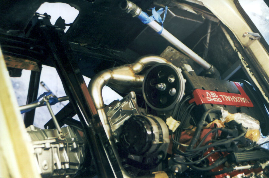
Once the rear hoop was tack welded into place, I got down to the serious process of putting things together. In figure 20 we see a similar view looking the other way into the engine bay. With the crossbeam in place and held in finger tight with the front two bolts on each side, the crossbeam could be squared to to the chassis to keep it clear of the reversing switch. Once tightened up, the remaining two holes were drilled at the back on each side of the crossbeam.
At the top of the picture can be seen the plumbing that's to go to the swirl pot. At the bottom on the right is a pile of wires for the ignition and fuel injection. The drive shafts have not been installed. The left one can be seen dangling in the centre left of the picture.
The next step was to put the rear suspension together as is shown in figure 21. Since all of the drilling had already been done, this was simply as matter of slipping the drive shaft onto the splines and attaching the control arms. In my case, both links were adjustable in length, and had been preset by Richard to have pretty close to the right camber, so all I had to do was hook them up, checking the bits of masking tape to see which bits were supposed to go on which side. When I came to do the second side, I found it much harder to get the holes for the links to line up. This was due to a very slight difference in the shape of my chassis from the one that Richard used (probably about 1/32"). I was able to adjust for this by adding a turn to each of the right hand links.
With the rear suspension in place the rear brakes and hubs could be put back together. To put the hubs back on I cleaned the old Loctite off the splines with a sharp chisel. This left the splines clean enough that the hub would just slide on firmly. Before putting the hub on I bolted the home-made hub plate to the hub with the lug nuts, and then put the hub on, applying blue Loctite to the splines and to the thread of the stub axle. I then tightened up the hub nut with a new tab washer to the requisite 150Ft lbs. Once the hub plate was removed the tab washer could be bent up to secure the hub nut in place.
Putting the brakes back together took a little thought, since I had failed to note which way round the springs go. The best thing to do is to note carefully how they go on the shoes. It's important to note that they will only go one way properly, and they go behind the shoes. The spring with the wire gap in it goes at the top, and the solid spring goes at the bottom.
I found that there was a little "H" shaped piece of metal that sat in the hole at the top of one of the shoes. On Richard's advice I took this out. As far as I could tell, all that it did was to prevent the shoe from touching the slave cylinder and thereby preventing the brakes from tightening up properly.
Putting the hub back on and adjusting the brakes involved another little bit of surgery. On Richard's advice, I measured the position of the toothed adjuster wheel on the slave cylinder to see where it lined up on the drum. I then drilled a 1/2" hole through the drum. This has to be done slowly by piloting once with (say) a 1/4" bit and then going straight to the 1/2". Don't use any lubricant, just drill slowly. Once you've got a hole in the face of the drum it is easy to adjust the brakes. Slip the drum over the shoes and, using a screwdriver, tighten up the brakes through the hole until the brakes begin to drag. Then, take a leather-faced mallet and tap the drum all around firmly, but not too hard. This will help to seat the shoes in the drum. You will then find that the brakes are freed up, and that you can spin the drum again. You just repeat this process until the brakes don't free up when you tap them. You can then back off the adjuster a couple of clicks and the brakes are nice and tight. This approach is good because it will work even if there's significant wear in the drum leaving a lip inside the drum.

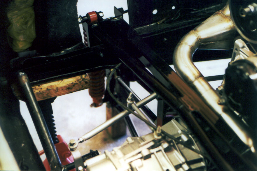
Figure 22 shows the top view of the suspension once everything is in place, other than the bolt connecting the brace at the top of the shock tower. I had not yet drilled the necessary hole when this picture was taken. The dark line snaking over the shift linkage is the speedo cable, which has to be kept out of the way during the welding of the rear hoop. The tack weld on the left-hand end of the rear hoop is just visible on the far left.
Once the drive train was in place that left three key subsystems incomplete; the coolant plumbing, the fuel system plumbing, and the wiring.
The coolant system came nominally with all of the plumbing already there ready to hook up. In principle, all I had to do was mount the new swirl pot on the side of the engine bay and hook things up. In practice, although things went pretty smoothly, getting the plumbing hooked up was not simply a matter of drilling a couple of holes and tightening up a couple of jubilee clips.
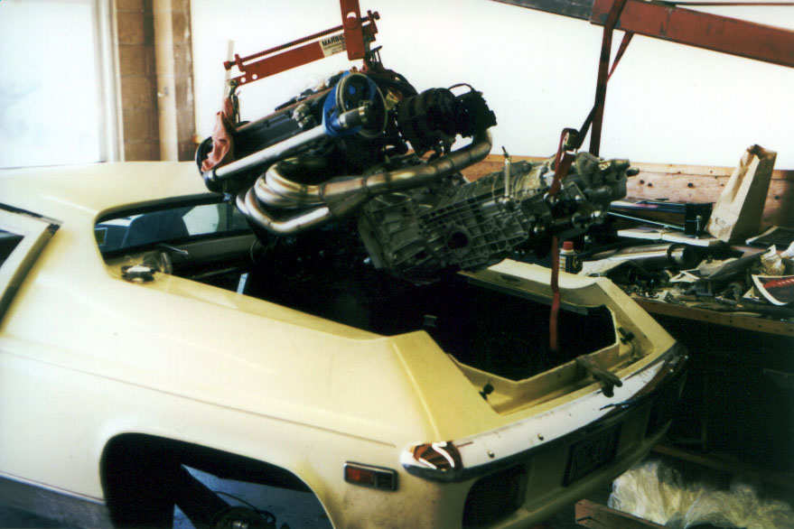
The first problem I had was that the plumbing that came with the motor had been hooked up on a chassis with no body work (I can hardly blame anyone for this). This is shown well here. The way this was done had two problems, the first was that without any bodywork there the dummied-up position of the swirl pot was a few inches outboard of its final position. This can be seen fairly easily here. This minor mislocation meant that although I had the right number of pipes, they weren't all of the right length, nor were they necessarily facing the right way.
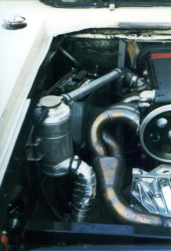
The second problem I had was that had I installed the swirl pot where the plumbing would have wanted it to go it would have fouled the pizza tray (rear luggage tray). This is an understandable mistake, since Richard is mostly focussed on building race cars and/or cars that aren't used for commuting. I ended up having to mount the swirl pot a fair bit further forwards and therefore had to shorten the pipes considerably. This ended up putting the downwards pipe from the swirl pot rather close to the exhaust. I ended up protecting it with a roll of heat shield tape. The swirl pot assembly is shown in figure 23.
Another problem I had was that I couldn't quite get the pipes to go around the rocking gate assembly correctly without fouling it. I ended up going to the radiator shop next door and grabbing a hose there with a bit more offset. It may be that this problem was caused by my having cut the coolant pipes short to a significantly different length from Richard. If I were to to it again, I think I'd get Richard to measure the length of pipe proud of the chassis spine bulkhead and draw me a template to aid in mating up the pipes.
On the other side of the motor I also had a few problems mating up the plumbing with the water pump. In practice, I found that the easiest thing was to take apart the plumbing that Richard had shipped me and shorten and/or adjust it piecemeal until things fit. I ended up getting a second hose from the radiator shop for this side too.
As I mentioned above, I now have a few problems with squeaks caused by the coolant pipes. Before you put the motor in I would suggest drilling the chassis to accommodate some sort of pipe clamps to hold the plumbing in place inside the box section of the chassis. These runs of pipes are fairly long, and not only do you not want them banging against things and squeaking, but you also don't want to stress them with excessive shaking around.
With the coolant plumbing in place, I pressed on to installing the fuel pump. The fuel injection requires a high pressure pump, and Richard shipped this along with a fancy looking high pressure side fuel filter mounted on an aluminium plate. I mounted this plate beside the right hand fuel tank on the inboard bodywork. I bolted it on a bit higher than the fuel line couplings on the tank with the electrical terminals facing upwards. Braided fuel hose then coupled the output of the pump to the input of the high pressure fuel filter, and from the filter up to the fuel rail above the throttle bodies. The fuel line from the T joining the tanks went through a small low pressure fuel filter and into the input of the fuel pump. Another section of braided fuel hose then got connected to the output of the fuel pressure regulator on the bottom, and this fed back to the T piece in the balance pipe for the fuel return to the tanks.
The wiring was perhaps the most daunting part of the process, though in fact things worked out pretty well. Everything that came with the new motor was excellent, with all of the wires colour coded and labeled with masking tape. The wiring that was in the car was a different matter. I had to contend with a considerable number of kludgey rewiring attempts by previous hands.
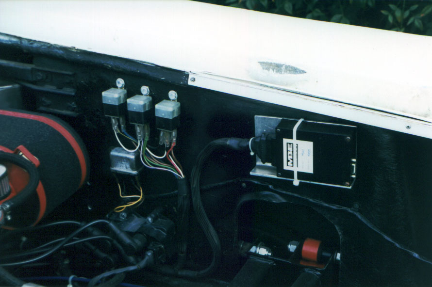
In practice, with all of the wiring already supplied for the Engine Management/Control Unit, all I had to do was hook things up. For reasons I still don't quite understand, the manufacturer of the ECU doesn't make a mounting bracket for the ECU. On Richard's prompting, I made an aluminium plate to which I stuck some self-adhesive velcro. This I then bolted to the side of the engine bay behind the right hand shock tower with a couple of spacers to make sure that I could zip tie the ECU to the plate once it was velcroed into place. I also organised things so that I could put another zip tie around the plug, thus making sure that it won't shake out. This is shown in figure 24.
The coils just bolt to some convenient spot on the right hand side of the engine bay. Before you mount them you should think about what sort of air cleaner you're going to use. I ended up having to move the coils because they fouled the air box (see figure 24).
With these larger lumps of wiring fixed to the car, all that has to be done is hook up all of the remaining dangling wires. To get everything in place you'll need a bunch of spade and bullet connectors, and a few eye connectors as well. The first problem that came up was that the plugs on the end of the old wiring loom going to the alternator didn't mate up even remotely with the new alternator. After another chat with Richard, I got it all fixed up. The tactic was to cut open the old plugs. This reveals four spade connectors; two big ones, and two small ones.
The big black wire has to end up with an eye connector and gets to mount on the end of the alternator mounting stud at the bottom. Be careful when you take the old spade connector off. At least in my case, the wire didn't have much slack to spare. The big brown and white wire goes on either one of the big terminals at the bottom of the alternator. The thin brown and yellow wire is for the ignition warning light, and goes to the small connector at the bottom next to the big wire. The remaining wire (brown/white) is not used. You could just cut it off, though I led it back along the loom and taped it in place - just in case I screwed up totally. The wiring for the alternator is visible in figure 29. You should check these details with Richard in case the alternator you get is different in some way.
Two wires from the new loom have to go to the fuel pump. These need eye connectors. It's important to get the connections the right way around on the fuel pump, of course. The polarity of the connections is marked on the pump next to the terminals, which are sized differently. Unfortunately, the pump came with neither nuts and washers nor with eye connectors. I found that the metric threads on the terminals didn't mate very well with the imperial sized connectors I was able to get at the local Radio Shack, and I ended up drilling out an undersized connector in order to get a pair of connectors that would ensure the polarity of the terminals. I would suggest preparing this stuff on the bench before you install the fuel pump. You will need a 4mm nut and a 5mm nut for the terminals.
Since my old tacho was shot, I had also got a new Elliot tacho from Richard. the cost of rebuilding the original was almost as much as a new one, and I wasn't concerned with an original look. The new tacho is wired slightly differently, and you have to run a wire for it from the engine bay especially. I ended up doing this by passing the wire down through the bulkhead in the spine of the chassis, and then up through the hole in the spine under the arm rest and from there along the top of the spine to the dashboard under the console. Had I thought to do this before I had the motor in place I might have tried to run the new wire along where all the others run, but it seemed too hard by this time. When the old tacho comes out, the two white bullet connectors that go into the back of the old tacho just get mated together. The other wires are hooked up as follows:
Ultimately, I was able to find the right festoons of wires to connect up to the starter. The terminals on the starter were clearly not designed to accommodate the number of wires that one gets on a Federal spec car piling up on the starter, so it was a little tricky to get everything on there, but ultimately possible. A similarly large bundle of wires connected to the earth point on the chassis where the diagonal brace used to be.
With all these wires in place the only connections I had yet to make were the main "-" terminal connection from the battery, which I connected to the bell housing, the water temperature sender wires, the remaining power connections for the ECU, the oil pressure capillary connector, the throttle cable, the speedo cable, and the clutch cable.
I found that there was a little trick to getting the speedo cable in place. Not only was it necessary to pull on the cable inner to make sure that there was enough sticking out, but I found it invaluable to use a mirror to make it possible to see down into the hole into which the cable goes. Unless you do this, you can be deceived into thinking that the cable has mated properly when it hasn't. The end of the cable outer is waisted, and you'd think that the plastic pin that's supposed to hold in the speedo cable would fit into the waist on the cable, but it doesn't, the cable has to go in far enough that the pin goes on the sloped part after the waist. It's easy to get this wrong, I found, since when the cable inner doesn't mate properly into the drive on the gearbox, the waist on the cable lines up perfectly with the hole for the pin, giving you the illusion that you've got it just right.
The oil pressure capillary is connected using an adapter that I took off the old motor. The motor came with an old electronic pressure sensor in its place. I suppose I could have reused this had I been planning to switch to an electronic oil pressure gauge, but I gather that the capillary driven ones are more accurate.
The clutch cable proved to be a slight problem. The motor came with a bracket to fit the clutch cable, but the cable wouldn't fit. Although the inner was (just) long enough to reach from the left hand side of the motor (mine is a LHD car) around to the right, the cable's outer was about 9" too short to be able to make it to the bracket. Luckily, inside the cockpit, the clutch cable fits into a little triangular bracket against the spine of the chassis. This bracket is held in with two rivets and two bolts. It was an easy matter to drill it out and move it back by the requisite distance. Getting it unbolted and put into its new location, though, was a two man job, since there was no good way to be under the car with a spanner whilst tightening from above.
The throttle cable proved to be a nightmare to get in place. Unlike the simple and efficient connector that one usually finds on Webers, the throttle cable mounts in a manner that's practically impossible to install. Like Webers in a similar configuration, the throttle cable mounts between the pairs of throttle bodies. That's as far as the similarity goes. The cable is gripped by a very curious little device that almost defies description. It's like a bolt only with no thread on the shank. The shank is the part that swivels in the cable mount on the throttle bodies, and it has a hole drilled crosswise, through which the cable passes. The cable is clamped in place by a long allen-headed grub screw along the axis of the shank, and up its centre. The remaining shank of the grub screw sticking out of the end of the other shank then takes a nylock nut and a washer.
The only way I could figure out how to fit this was to screw the grub screw in tight with the assembly out of the car, and then screw the nut over the grub screw until it was almost as far on as it would be when tightened all the way up. I then undid the grub screw taking the nut and washer with it. I then took off the bracket onto which the throttle cable outer mounts and cut a slot in it to allow the cable inner to pass through, but not the ferrule at the end of the cable outer. This would give enough slack in the cable to be able to install it. I then put the screw assembly into place using the nut on the end of the grub screw to give enough purchase to get it in. This is very fiddly. It was then possible to slip the throttle cable inner through the screw assembly and tighten it up with a spanner on one end and a small allen key on the other. Once the grub screw was tight on the cable inner, it was a small matter to tighten up the couple of remaining turns on the nut, leaving a little slack so that it could swivel, and then slip the cable inner through the slot in the mounting bracket. I should note that this was only possible at all because at the time I had no air filters in place. With any sort of air box in place, this whole process would be impossible.
Getting an air filter proved to be a lot harder than I had expected. Richard had said that it would be easy to get "sock" type air filters that I would zip tie on over the bell mouths. This proved no to be the case. For whatever reason, such air filters proved to be really hard to get in the US. I tried talking to the technical support people at K&N, and they were pretty clueless, though they did end up sending me a huge catalogue that arrived weeks too late for me to be able to use it. After much phoning around, I managed to track down a dealer for ITG filters (TWM Induction - 805-967-9478). The chap I talked to there (Gary Pollard) was pretty clued up, and even knew the motor I was talking about.
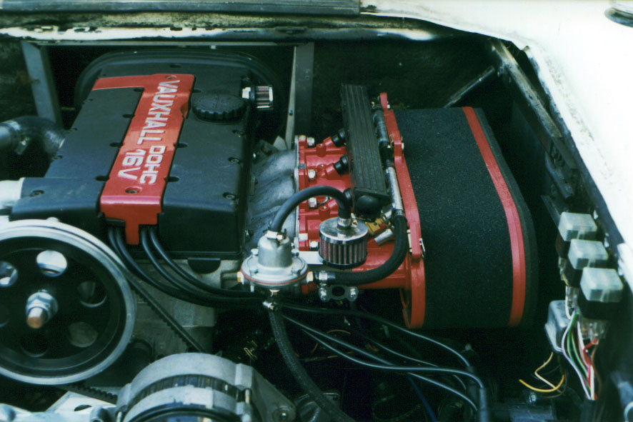
The reason why getting a filter assembly such as K&Ns to fit it so difficult is that the bell mouthes are large relative to the size of the normal kind of backing plate that one would use. Even though the spacing and drilling of the throttle bodies is the same as for 48mm Webers/Dellortos, the bell mouthes come so close together and are sufficiently large that normal K&N backing plate assemblies and filters won't fit. Anyway, the ITG filter is just fine, though expensive, and they will cut a backing plate for you to the right dimensions. If you do this, you should measure the separation of the centres of the two middle throttle bodies, but it should be the same as mine, which was 102mm. You then need to ask them for an ITG JC50/100 filter and a 00-JC-50 backplate drilled to 102mm. Note that you need to specify that they should not drill the extra breather holes that are normal for Webers. You will also need a can of filter oil, which is different from K&N oil. In my case they threw in the oil, since there was already a non-trivial upcharge for the backplate drilling. I seem to recall that they carry backing plates at 101mm and 103mm, but if you want to do it right, you'll have to get the non-standard drilling. The whole filter assembly came to $176.69, which is pretty expensive for an air filter, but it turned out really nice, and I'm very pleased with it. The filter is shown installed in figure 25.
There are two other places where you may end up putting filters. You'll need to do something about the valve cover breather holes, and you may want to plug the hold on the fuel pressure regulator with a filter as I did. The valve cover actually has two breather hole. One I plugged with a vacuum plug, the other I plugged with a filter. The two filters I used are also shown in figure 25. I mounted the filter for the fuel pressure regulator on a left-over piece of L-section extrusion. The filters in question are:
The power connections for the ECU come from where the old coil used to be. The best thing to do to find the right wire is to check with Richard, you don't want to get this one wrong.
There are two temperature senders on the motor; one that goes to the dashboard and one that goes to the ECU. The one for the dashboard ended up being the one from the old motor. Sadly, although Richard had got pretty well everything in place, due to a last minute screwup, he didn't ship the temperature sender for the ECU. Unfortunately, I didn't know it was missing until I was right near the end champing at the bit to get the motor running. Without the temperature sender you can't put in the coolant, so you're stuck. Richard rapidly sent me one, and it arrived in a few days, which gave me a little time to work on the exhaust bracket, and other bits and pieces. Since the radiator was in bits to re-core, I had the radiator shop move the fan mounting straps and studs to accommodate the new fan, and replaced the mounting studs on the bottom, which had disintegrated when I took the radiator out. All told, the new arrangement is very nice, quiet, and cools really well. When I had the radiator out, I discovered that about an inch on either side of the cooling area of the radiator was not being used due to being blanked off by bits of bodywork in the wheel well. By this point I was already fearless about cutting holes in my car, so I decided to cut these back. This seemed to be an easy way to pick up about an extra 13% of cooling area.
The only problem I had with getting the new cooling system to work was a little trouble with the wiring. It turns out that the original fan is wired upstream of the switch, and the switch is connected to ground on its downstream side. When the switch closes, the fan comes on because it grounds through the switch. It turns out that the new fan, although it has two wires, grounds itself, i.e. its ground wire is redundant. If you wire it in like the original fan it will be on all the time. You need to change the wiring slightly to move the switch to upstream of the fan.
Figure 26 shows the re-cored radiator with the new Mercedes fan in place. The wiring hasn't yet been fully cleaned up, but the new fan switch can be seen just to the left of the air horns.

The only really serious piece of fabrication necessary was the making of a bracket to support the tail end of the exhaust. Richard said that he didn't make this piece because differences in lineup are large enough from one car to another that he can't sensibly do so.
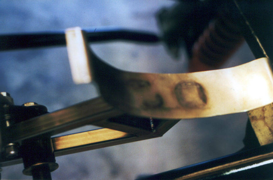
Figure 27 was taken when the motor was in place, and I was making the exhaust bracket. The bevel gauge I'm holding was to mark off the angle of one of the pieces for the bracket. The smug grin is because I'm looking forward to starting the car, which I did the next day. Had I known that it was then going to puke oil all over the place and require me to drop the gearbox out, I might not have looked so happy.
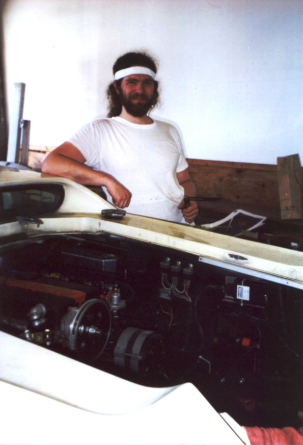
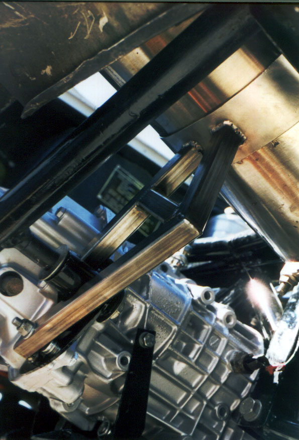
Figure 28 shows this bracket just after I installed it, but before putting the muffler on. The exhaust Richard supplied does not poke out under the bottom of the car like the original one, it comes right out through the back of the car to the right of the number plate and to the left of the right hand tail lights. I found that in my case it wasn't quite possible to get the muffler on to the rest of the exhaust far enough that it would clear the back of the car and swivel into place, so I had to shorten the L-shaped section of exhaust into which the muffler fits. This was easy to slip off and cut. Once this was done, the muffler fitted in fine, and swung down into what was intended to be its final location. I centered the hole for the tail pipe in the back of the car by wrapping a piece of heavy paper around the tail of the muffler and tracing around it onto the inside of the back of the car. This step solved the problem of figuring out where to cut the final hole in the back of the car. A 4" hole ended up being exactly the size of a standard tub of grease, so all I had to do was trace around it and cut the hole out with the Sawzall. Fibreglass is fairly easy to sand smooth, so it doesn't matter too much if you're not very accurate in cutting the hole. Once you've got the hole cut you can slip the tail pipe onto the muffler and see what the final result will look like. Although you shouldn't have clamped the exhaust up at this point, it should be easy enough to support to be able to hold it in place for you to make the muffler bracket.
I made my bracket by ripping a piece of wood to 3/4" square. This would mimic 3/4" box section steel. Given these bits of wood, a coping saw and a drill it was easy to make a template of wooden bits that went from a couple of available mounting points on the side of the gearbox up to the muffler. I used bent coat hangers to hold the wood in place up against the muffler until I had the shape fixed in place by screwing the wood to a scrap of plywood. I was then ready make the steel version of the bracket. Foolishly, I thought it would look really good to carry the stainless look of the exhaust through to its bracketry, and decided to make it in stainless steel. The end result is indeed very pretty, but it was a nightmare to make. Stainless steel is very hard to cut if you don't have the right tools, and even if you do it's hard to cut at the funny angles that are likely to be necessary. I ended up getting a three-pack of carbide granule coated Sawzall blades (about $13) and they did the trick, but it took a long time. Life would have been much easier had I just done it in mild steel and power coated the result. All in all it took about a man day to make the bracket, which is way out of line with the significance of the piece.
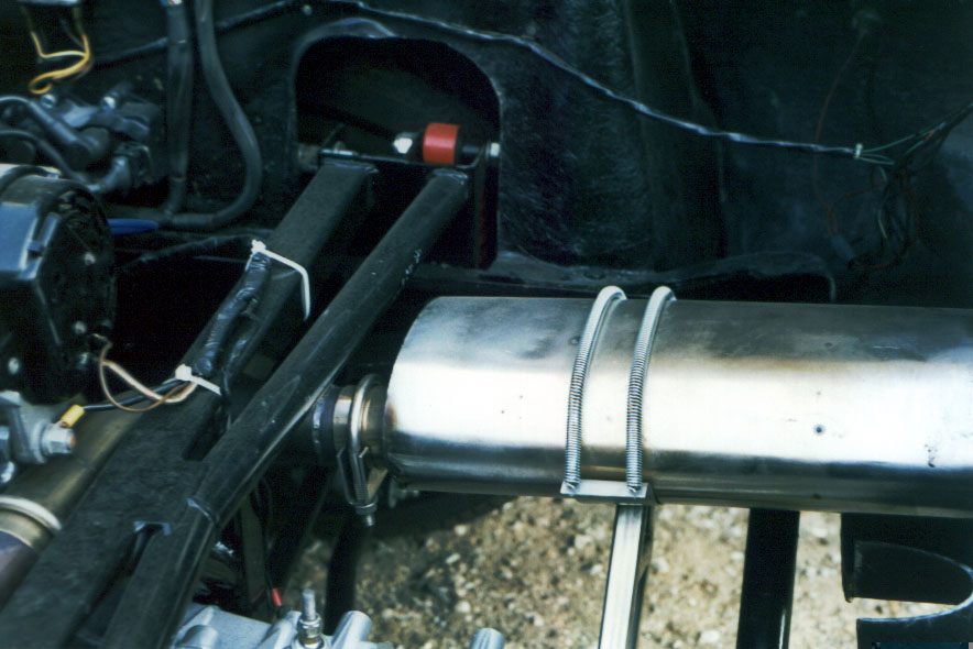
Once I had the pieces cut out for the bracket, I had them welded up by Jon Zender, a fellow Europa owner, who is also a high-tech welder. The cradle in which the muffer sits was made out of a piece of stainless sheet bent to fit. It was then bent over at the ends and drilled to accommodate a pair of 6" springs that I got at the local hardware store. The way the springs locate on the bracket is shown in figure 29.
While you've got the Sawzall out, you'll probably want to cut off the top of the bulge in the bodywork that used to accommodate the final bend in the old exhaust's tail pipe. This bulge comes up pretty close to the new muffler unless you cut it down a bit. The result is visible on the right of figure 29
After the bracket was welded up, I found it didn't fit quite right, even after taking my template and a traced out pattern of the bracket over for welding. It was simply too hard to get the complicated angles lined up right. If you can't at least tack weld up the bracket in situ on the car, I would suggest making enough of a template to be able to hold the holes for the gearbox end mounts in their correct position. I fixed the fit problems by judiciously adjusting things on my mill.
The final bracket arrangement is shown from below looking up at the muffler is shown in figure 30. The motor shipped with a complete exhaust except for the clamps. Richard said that it would be easier to get nice stainless steel clamps in the US than in the UK. I actually found it to be pretty tricky, but eventually managed to track some down. I ended up using Borla clamps. I called their head office and got put onto their Bay Area distributor, which had a number in stock.
Once everything that had to be connected was in fact connected, and everything looked good, I decided that the time was right to weld up the rear hoop. Like the removal of the old rear hoop, the welding of the new rear hoop into place is a fairly non-reversible process, so it's better not to do it until you're absolutely sure. Once it was welded in place I could paint it.
At this point, the car was ready to fill up and to start. Filling up the coolant system took a five litre bottle of antifreeze and about another five litres of water. The motor took somewhat over five litres of oil (20/50 for the initial running in period and synthetic 15/50 after that, e.g. Mobil One, or Valvoline Synpower). The gearbox took a bit under three litres of 75/90 synthetic gear oil. With these in place, I cranked the motor a number of times for a few seconds to get some of the oil around into the key places.
I was then ready actually to try to start up. I got a gallon of petrol, put it in and tried things. When you turn on the ignition, the fuel pump whirs for a couple of seconds and then shuts off. I found that it took a few tries of actually trying to start the motor for it to catch, so I suspect that it may be a good idea to turn the ignition on and off a few times to make sure that the fuel is well pumped through the system. I suspect that the fuel pump doesn't run continuously until the motor is actually running (a good safety feature).
So, notwithstanding the fact that it took a couple of tries for the fuel to get to the motor, it started effectively first time. That was the good news, and things sounded fine. Eric was standing by the engine bay looking for problems, and I was in the cockpit cranking things. Everything looked good for a few seconds, and then oil started to puke out of the motor onto the floor. Not a good sign. I noticed that the oil pressure gauge seemed to peg itself too, which was a little disconcerting. The oil seemed to be coming from the middle of the motor between the clutch and gearbox. I decided that the best thing would be to shut down and call Richard to see what oil pressure I was supposed to expect, and see if he had any ideas.
He told me that I should expect about 60lbs of oil pressure on the new motor with thick oil in it, maybe 50lbs after running in. This was a null data point, since my oil pressure gauge only read up to 60lbs, anyway. He suspected that the oil pressure relief valve might have dried out in transit, which might be causing the oil pressure to run open loop. This would result in the pressure being very high (maybe as much as 150lbs). If this were so, there was a chance that the crankshaft main seal might have blown out or turned inside out, thus letting oil puke out. Richard said that the pressure relief valve sticking is very rare, but is not unheard of. I would strongly suggest taking it out and making sure it's unstuck before you put the motor in. It's well worth the five minutes it would take with the motor out of the car, just in case.
With great fear and trepidation, the next day I took out the pressure relief valve to clean it. It's located at the front left of the motor on the block just above the sump gasket line, behind a hex-headed cover, which looks like a big bolt head. When you undo the cover the spring pops out, and in my case, leaves behind the plunger for the pressure regulator. With a little jiggling around with a pair of circlip pliers I was able to get it out. It looked fine, but I polished it up with some emery cloth and fiddled around in the hole with my finger to see if I could find any obstructions. Everything seemed fine, so I put everything back together with lots of oil. Reassembly was a nightmare, since it's very difficult to get the right purchase on the head of the cover to screw it in against the pressure of the spring. There's a definite knack to it, but you won't have that knack the first time you do it, so that's why I think it's a good idea to do this with the motor out of the car.
With the pressure relief valve all back in place I tried starting the motor again. Again it started first time, but again oil puked out. That meant that the seal had either turned inside out, or had blown out. So, once more I called Richard up and asked him to send me a new main seal and probed him for any tips that might help me pull the gearbox out.
A couple of days later the FedExed seal arrived, so I started work at pulling the gearbox. This turned out to be theoretically a simple process, but in practice was a major pain. Superficially, all one has to do is remove half a dozen bolts and the thing should separate from the rest of the motor, but that doesn't deal with all of the other stuff that gets in the way of removing the gearbox. In practice, I found that I had to remove all sorts of bits and pieces starting with the muffler, the shift linkage and clutch cable, and moving rapidly on to the speedo cable, reverse light wires, alternator, suspension links, drive shafts and the chassis crossbeam. With all this stuff out of the way, the gearbox seemed to be held in only by the bolts connecting the bell housing to the adapter plate, and the two bolts fixing it to the rear hoop. With a jack under the tail end of the motor, the gearbox slipped off pretty easily. I loosened the front motor mounts a little so that I could tip the motor a bit to get a bit more clearance. This let me lift the gearbox up and out, tail end first. The gearbox and bell housing together weigh around a hundred pounds, so it's reasonably easy to do on your own, but you'll need to figure out how you're going to get it out of the car if you're standing in the engine bay. In my car I passed it to Eric.
The clutch is bolted to the flywheel and comes off easily by loosening the bolts on its circumference evenly. This lets the pressure plate and driven plate come off together, revealing the flywheel. The thing to do next is to mark the flywheel's alignment onto the crank with chalk so that you can get it back on in the same orientation. The flywheel is held on by bolts which are easiest to take off with an impact wrench, since they will have been Loctited into place, but you could take them off by locking the crank either with a spanner at the other end, or by wedging a screwdriver between the ring gear and the adapter plate.
Once I had got the flywheel off I was faced with the end of the crank. I had asked Richard how to get the old seal out, and he had said that the thing to do was to drill a little hole in it and use a self-tapping screw screwed into the hole to push it out. However, once I got the flywheel off I discovered that there simply was no seal. It had never been put in. This is an easy mistake to make, but Richard was duly embarrassed by this omission. I tried to take it well, but the day I did this work was 103 degrees outside and considerably hotter in the garage, so I wasn't too delighted by the end of the day. This is an unfortunate problem of shipping a motor without the motor actually running in a car before it's shipped. It was wonderful that Richard built everything for me in a chassis, but I suspect that if I were to do it again I'd ask him to dyno the motor before shipping it. That should expose any problems such as this. It's not cheap, but time is money during the installation too.
Putting the flywheel on is just a matter of aligning the marks you've made, and bolting it on, using blue Loctite on the threads and torquing to about 55lbs.
The reassembly of the clutch takes a little care. Richard told me that I could just use a universal alignment tool that was bound to be lying around the garage, but this proved not to the the case. All of the alignment tools were all for the specific flavours of Jag or Aston Martin that Eric worked on. I went and bought a universal alignment tool, which claimed to have the right (21mm) size to fit the pilot bearing, but when I tried to use it, I found that the adaptor for the pilot bearing had a lip on it that was intended to rest on the end of the crank, but since the inside diameter of the splines on the driven plate was only just over 21mm, the alignment tool wouldn't go through the driven plate. I managed to grind it down so that it would fit on a bench grinder, but life would have been much easier with the right alignment tool.
The next job was to make sure that the driven plate was the right way around - it's usually stamped on one side saying "flywheel side", but you should note which way around it was carefully when you take the clutch off. If you get it wrong, the cush springs will scrape against the bolts on the end of the flywheel. I then tightened up the pressure plate progressively and diagonally to about 15lbs. Before mounting the bell housing back onto the motor, it was necessary to drift the dowels out of the bell housing where they had stuck when the bell housing came off, and put them into the adapter plate. Doing it this way around makes sure that the dowels don't push through into the bell housing as you tighten the bolts up. It's important also to remember to grease the splines on the gearbox main shaft with a suitable ultra-high temperature grease such as Copperslip. Reassembly of everything else proved to be a simple reverse of the disassembly process, with the only major problem being the throttle cable, which was a nightmare as already noted above.
When I installed the throttle cable, it was a little longer than necessary, but I decided that it would go well if I led it down the left-hand side of the motor, and then through a little eye at the bottom of the gearbox. This forced me to remove the throttle cable to take the gearbox out, and when it came to putting the cable back, I found that I had to remove the injector stacks and the air box assembly to get to the throttle cable adjuster.
Similarly, because I had put no thought to disassembly when I put the motor in, I had led the heater control cable through the bracket for the alternator. This seemed like a nice way to support it and keep it neat, but was just another minor headache when it came to taking the gearbox out. I would recommend against such undue cleverness, and advise just using zip ties all over the place.
Once I had got the gearbox back in place, I found the car started first time, again, and this time didn't puke oil. I was ready actually to run the motor for more than a few seconds. Things seemed to run well and, with the car still up on its jack stands, I tried to find all of the gears. I found that I couldn't get to reverse without the shift linkage fouling the gearbox adapter plate. Luckily, the shift linkage has numerous points of adjustment, so it wasn't difficult to remedy the situation. I also suggested to Richard that he change the template slightly for the adaptor plate. I was fouling on a piece of the plate that didn't need to be there anyway. With any luck, he will have changed the design in future to reduce the possibility of this problem.
I was then able to drop the car down on its wheels as shown in figure 31.
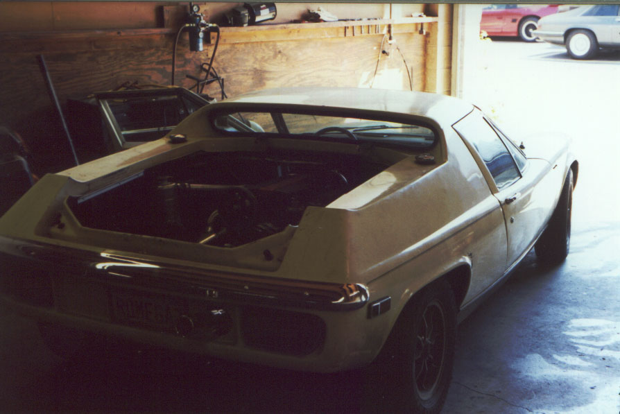
Figure 32 shows the car in the same state just getting ready for a test drive. It's important to check all of the vital fluids in the car. It probably won't have been very level on its jack stands, and you will probably have air pockets in the coolant system. Once the motor has warmed enough for the thermostat to open you may find a significant drop in coolant level. If you run the motor with the radiator cap off you should see water pumping fast through the swirl pot once the thermostat opens. Be careful about adding more water with the motor hot, since you might get steam blowing back a fountain of boiling coolant all over you.
When I came to put the bonnet and boot back on the car I decided to make a minor modification to the boot. I drifted out the pins in the hinges (note they will only come out one way) and replaced them with a couple of 3/4" x 3/8" clevis pins that I got from a local boat chandler. These let me remove the boot lid in a few seconds, but are rather more secure and less obvious than pit pins. This way I hope that I won't suffer too many people breaking into the boot by noticing that the hinges break apart.
Once I started to drive the car, I found that it was not behaving as I expected, especially once it had warmed up. The motor didn't seem to pull well, wouldn't rev freely, and back-fired all over the place. I called Richard about this, and he said that this was due to a tiny miscalibration of the throttle position sensor. If this sensor is slightly off, it makes the ECU think that the motor is in a completely different part of its performance map.
The fix for this was to borrow a laptop PC from a chap at the office, download the ECU programming/telemetry software, and plug the PC into the ECU with a standard female DB9 to male DB9 serial cable. With lots of instructions from Richard I was able to adjust things by loosening the two clamping bolts on the throttle position sensor body on the back of the throttle body assembly and tweak the setting whilst looking at the readouts on the screen. Once this was done, the motor ran a thousand times better, and has been doing fine ever since.
With the car fully running, I was able to concentrate on the remaining problems. The first to appear was that the speedo drive ratio was way off. I got a suitably calibrated one from Richard. I held off doing this until I got new tyres to make sure that I calibrated for the right final drive ratio. Incidentally, Richard recommended 185/60-13s all round, running at around 16-18lbs at the front and 24-28lbs at the rear. I'm currently running at 16/25lbs with Yokohama "AVS Intermediate" tyres. I picked them because they're the stickiest tyres I could get that still had a full rain tread - remember that this is my wet weather car.
Now that I have the new tyres in place I'll be able to set up the suspension properly, though I haven't got around to it yet. Richard recommends 1.25 degrees of negative camber on the rear wheels and 3/32" of toe-in as measured between the front and back of the rear wheel's rim. Apparently, it's really difficult to get enough toe-in, and getting any at all is pretty good. It's apparently possible to get more toe-in by moving the radius arm mounting pivot so that it bolts to the inside of the chassis rather than the outside. It's also apparently possible to shorten the tube at the end of the radius arm through which it pivots simply by sawing it off. I'll look into this when I find out how far out I am in the setup.
The one remaining problem I have is that the alternator intrudes into the space that the pizza tray should occupy. As we have already seen, I took some trouble to make sure that the swirl pot wouldn't get in the way of the pizza tray. I haven't yet fully fixed this problem, but I've got so far as to cut out the necessary hole in the front of the pizza tray, and relocate the heat shield on the bottom so that it more accurately matches where the new muffler goes. The tricky part will be dealing with the curve where the bottom of the pizza tray meets the front, and dealing with the fact that any box I make to cover the alternator will have to mate up with one of the ribbed parts of the front of the pizza tray.
Now that I've just put the first 500 miles on I've just done the first oil change. This turned out to be a nightmare. The car is now sufficiently low that I can't get the oil pan under the sump without jacking it first. Rather too late, I discovered that the oil pan I was using was too small to accomodate the extra oil held by the new motor (about 50% more). Next time I do this I'll put it up on the lift. I also had a problem finding the right oil filter, since the motor is unknown in the US. As it happens, effectively all of the smaller GM four and six-cylinder motors use the same filter, which in the US is one of:
| Make | Model |
| AC | PF47 |
| Carquest | 85040 |
| FRAM | PH3387A |
| Motorcraft | FL321 |
| NAPA | 1040 |
| Purolator | L10111 |
| Wix | 51040 |
| Big A | 92040 |
I also have to finish off the trim panel on the cockpit side of the firewall, but none of these problems are stopping me from driving the car.