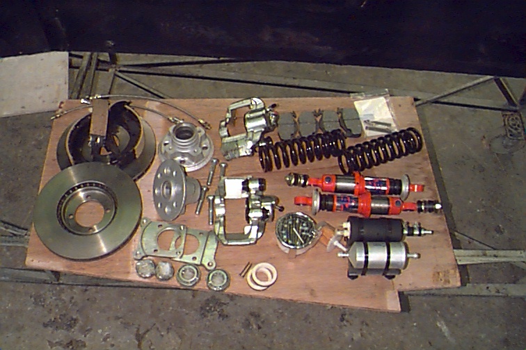
This is a random collection of new brake and
suspension bits: New front vented discs and calipers, hoses, rear
shoes, new dampers and springs all round, front hubs and bearings,
fuel pump/filter assembly, and a tacho.
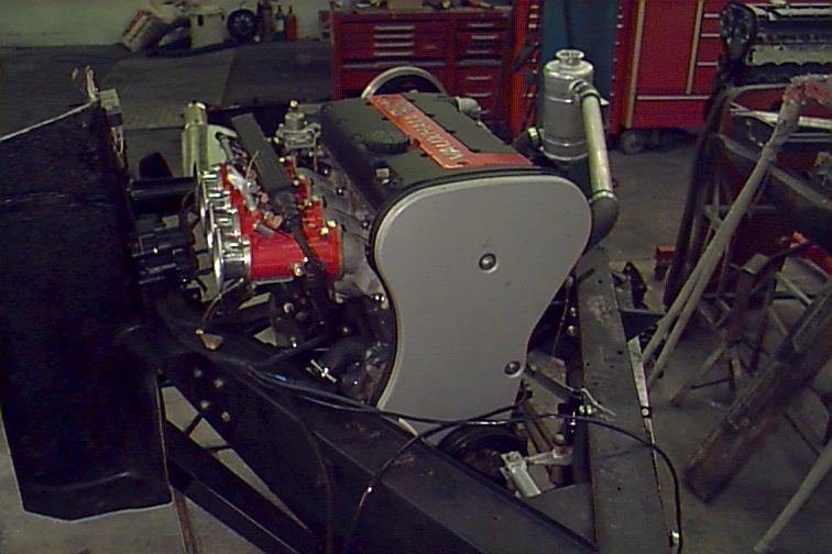
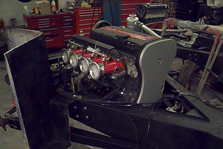
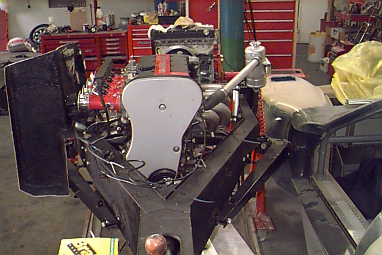
View of the motor from the front right sitting in a spare chassis they had. The red bit is the throttle body assembly for the digital fuel injection system. To the left are the air horns (silver).
Looking down at the front of the motor showing the rocking gate assembly for the new gear shift linkage. The pulley at the bottom of the motor is not used.
Another front right view of the motor.
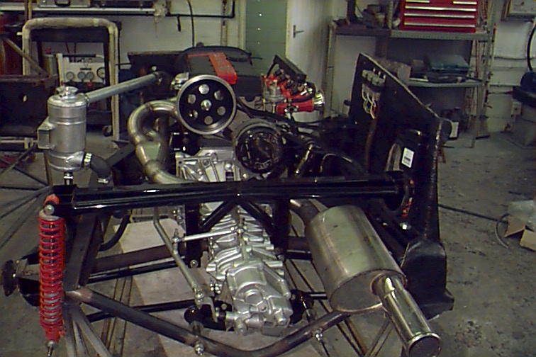
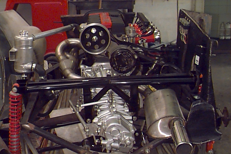
Rear view showing new exhaust, gearbox and shift linkage as well as the new rear shocks and the twin-link rear suspension system. The big pulley in the middle drives the alternator. The black bit of bodywork on the right is a dummy for the right hand side of the engine bay. The white blob by the right hand shock tower is the engine management computer. The unpainted tube running below the gearbox is the new rear hoop.
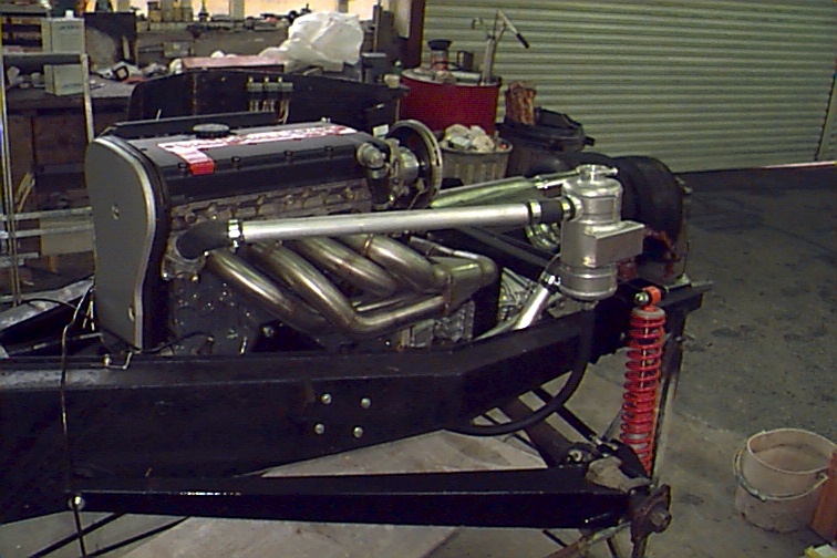
View of the left side of the motor showing the exhaust headers and coolant swirl pot. At the bottom is the left hand suspension radius arm.
Rear left view shows twin-link suspension and swirl pot.
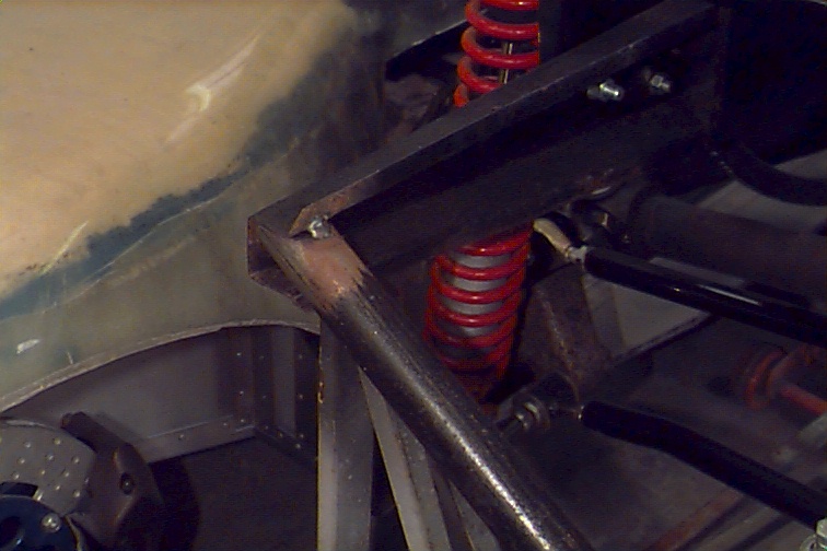
View of the left rear corner where the new rear hoop meets the rest of the chassis (just tack welded in place). The old hoop had to be cut and ground out, and the new one welded into place to accept the different mounts on the new gearbox. It's unpainted because it has to be welded in place first.
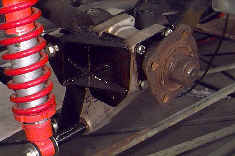
Detail rear right view of how the twin-link assembly mounts to the hub carrier. The rusty bit on the right is the hub with the drive shaft coming in diagonally from the top left.
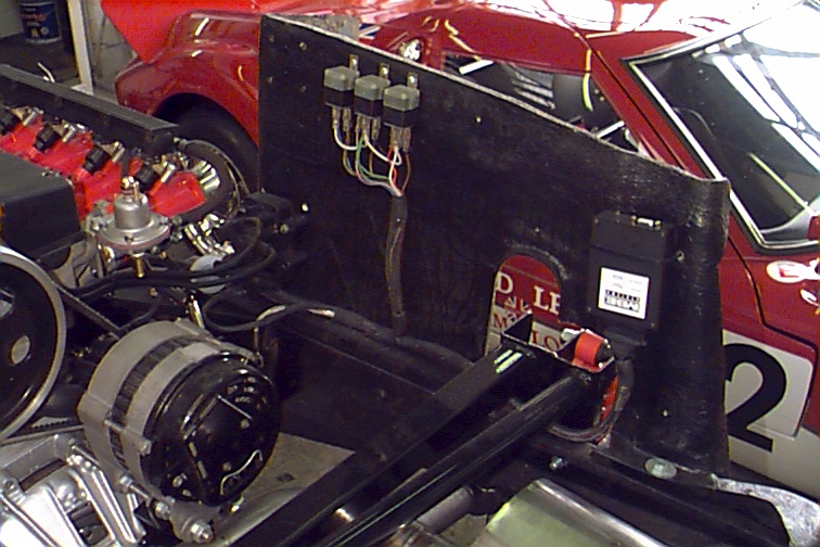
Detail of right hand side of engine bay showing engine management computer, relays, wiring loom, and coils (black blob at bottom left of the piece of bodywork). The fuel pressure regulator is mounted just aft of the throttle bodies.
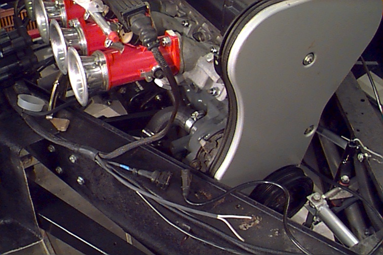
Detail of front right hand corner of motor showing wiring loom where it connects to the the rest of the wiring system and to the fuel pump. The water pump is in centre frame behind the cam belt cover. The shift linkage mount for the rocking gate is also shown. The milky looking blob on the left is just a shipping cap for one of the throttle bodies, which has fallen out.
View from front showing the spine of the chassis. The shift knob is at the bottom of the frame.
Another rear view.
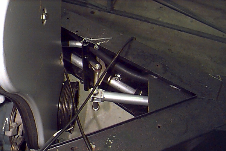
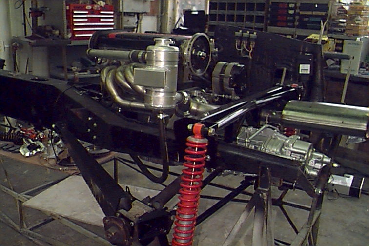
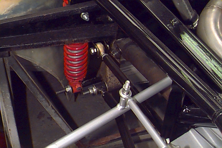
Detail of left rear corner showing the shift linkage (silver) and the adjustable suspension links (centre) running under the new chassis cross beam (shiny black bit on the right.
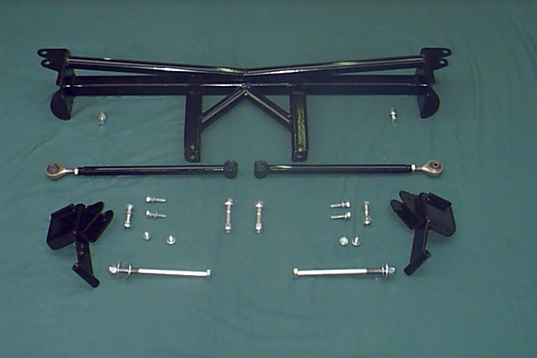
Detail of the parts for the twin-link suspension system. Mine actually has two sets of adjustable links. This picture only shows the upper pair running across the centre of the frame.